Pumpensumpf
Six Summers of Water
Six years ago we did the obvious thing. Austrian summers had stopped pretending to be temperate, our flat is on the top floor, and 30 °C indoors is the temperature at which a person stops having opinions and starts having grievances. So: air conditioning. Outdoor unit outside, indoor units inside, everybody happy.
Everybody was, in fact, happy. Except for one detail, and the detail was water.
An air conditioner is, thermodynamically speaking, a machine for moving heat. Practically speaking, it is a machine for producing condensate. Every hour it runs, it wrings water out of the air, and that water has to go somewhere. In a normal flat, “somewhere” is a drain located conveniently downhill. In ours, “somewhere” was the roof — two floors up. Which means pumping.
The Pumps That Came With It
The installers fitted the standard solution: small condensate pumps at the indoor units. These worked, in the sense that water did leave the building. They also had two qualities I had not budgeted for.
They were loud — a thin, insistent whirr with a distinct mechanical personality. And they ran whenever they felt like it. Not “when there is water”, which would be defensible, but on some private schedule known only to themselves. At 02:00. In a bedroom. In summer, with the windows open, when the whole point of the air conditioning was to make sleep possible.
I do not consider myself an unreasonable person. But there is a specific flavour of rage reserved for being woken by the machine you bought in order to sleep better.
The Idea
We had already repurposed the flat’s old chimney as a cable duct — the lines between the outdoor unit and the indoor units run down through it. A chimney is a vertical shaft with a service door at the bottom and a hole in the roof at the top. If you were designing a building specifically for the purpose of collecting water at the bottom and pumping it to the top, you would design a chimney.
So: one central collection vessel at the base of the shaft. All the condensate lines feed into it by gravity. One pump, one pressure line, up and out. One pump instead of three. One noise source instead of three, and that noise source safely at the bottom of a masonry shaft two floors below anyone’s pillow.
It is a good idea. I still think it’s a good idea. That’s the trouble with good ideas — they get you to start.
The Ritual
What followed was, and I want to be precise here, six years.
The loop went like this. Build a version. Install it in the chimney. Enjoy roughly one blissful period of correct operation, lasting somewhere between three weeks and most of a summer. Then, always at night, always in July, discover that the chimney had quietly stopped being a chimney and become a cistern.
And then the ritual: kneel at the chimney door, feed a hose down into the shaft, put the other end in my mouth, and siphon out several litres of lukewarm condensate that had been sitting in a brick shaft since roughly the previous Tuesday. Then bucket. Then towel. Then bed, at 01:00, tasting like a heat exchanger.
I did this more times than I am willing to write down.
Every single failure was, in retrospect, informative. At the time it was informative the way a hangover is informative.
| Version | How it failed | What it was trying to tell me |
|---|---|---|
| Electronic level sensors | Read a level that was not there. Ran the pump dry, or didn’t run it at all. | Condensate leaves deposits. Anything that senses without moving will eventually sense wrong. |
| Horizontal float switches | Jammed against the vessel wall, or against the pump, and stayed jammed. | A float needs somewhere to be. Guaranteed clearance is a design requirement, not a detail. |
| Assorted control circuits | Simply gave up, usually silently. | If the pump can’t run, the water level is not going to negotiate. |
| Home-made vessels | Leaked. Every time. At the seam, at the feedthrough, at the joint I was proudest of. | Watertight is a property of materials and geometry, not of enthusiasm. |
| All of the above | Chimney full of water | Hose. Mouth. 01:00. July. |
What Six Years of Failure Taught Me
By the end I had a specification. Not one I derived — one I was issued, by physics, one wet chimney at a time.
- The switch must be mechanical. No probes, no capacitive cleverness, no electronics touching the water. A float, a rod, a magnet, a reed contact.
- The switch must be vertical, with two switching points. One float says “start”, the other says “stop”. Two points mean the pump runs a real cycle and then rests, instead of chattering at the surface.
- The switch needs a dedicated controller. The XH-M203 is a small relay module built for exactly this kind of dual-float setup: high float latches the relay on, the pump runs, the level falls, the low float releases it. Hysteresis, in hardware, for about six euros.
- The pump must be small enough to fit in the pipe and strong enough to reach the roof. These pull in opposite directions, which is why it took a while to find one that does both.
- The float and the pump must live in separate chambers. This one took me the longest, and it is the whole design. More on it below.
- The vessel must fit through the chimney door, accept 3D-printed parts, and not leak. Three constraints that eliminate almost everything.
That last one is how I ended up building the entire thing inside a piece of sewer pipe.
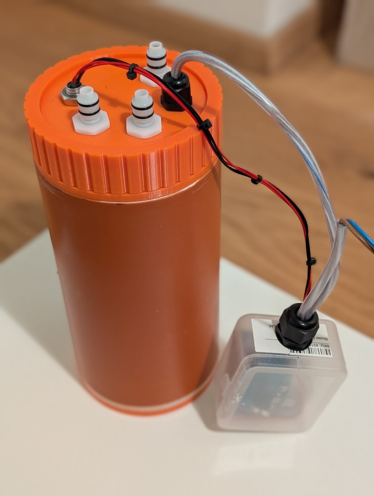
The Design
The hard constraint is Ø110 mm. Nothing, anywhere, at any point, may exceed it — that is what fits through the chimney’s service door and down the shaft. Everything else is negotiable; this is not.
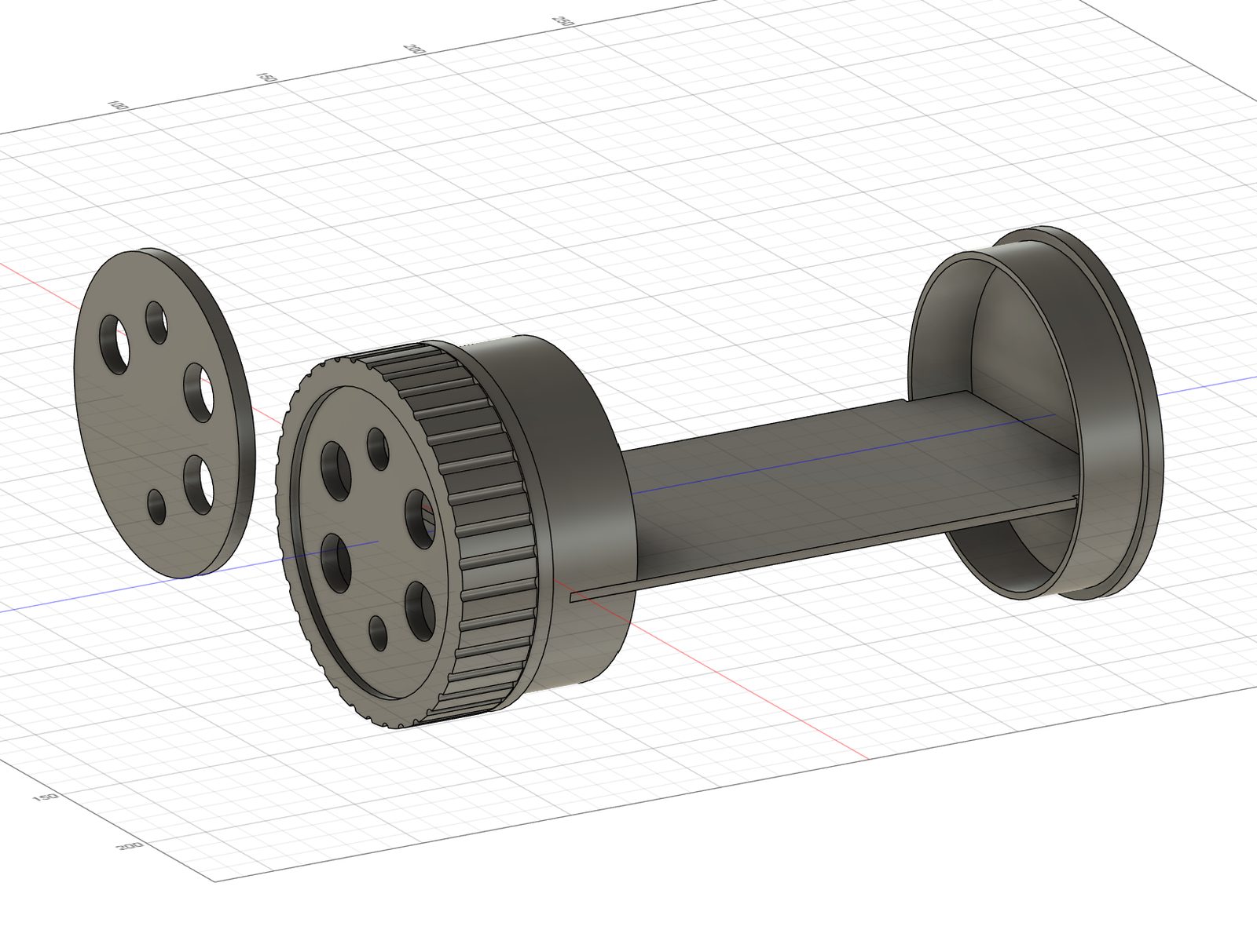
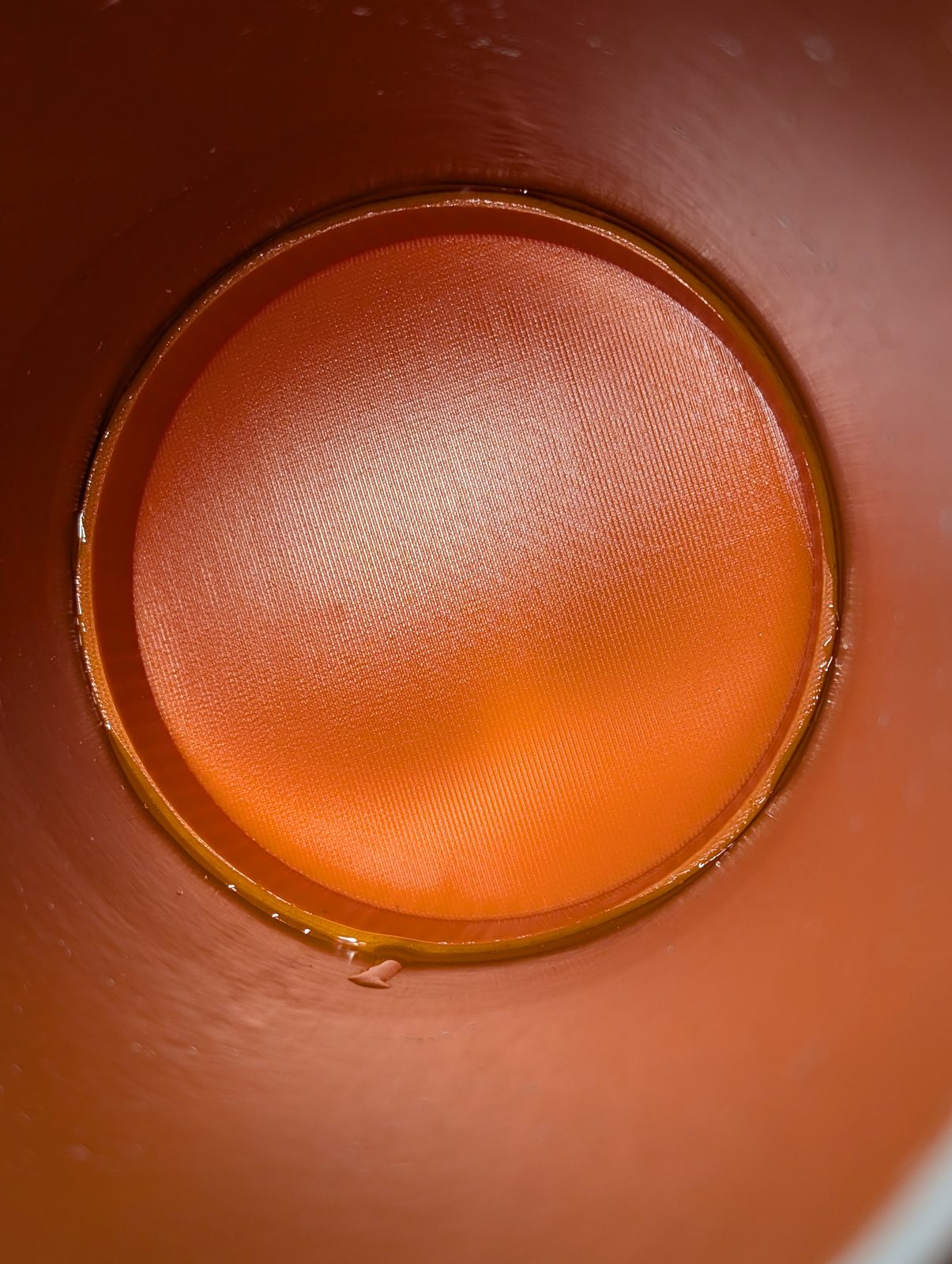
So the vessel is the pipe. A KG pipe DN110 — the orange PVC stuff used for buried drainage — cut to 200 mm. A printed floor closes the bottom. A printed insert closes the top and does three jobs at once: it seals, it carries the screw thread, and it holds the divider that splits the interior into a pump chamber and a float chamber.
The closure is a mason jar. Insert with an external thread and an O-ring groove, a lid that drops onto the O-ring, a union ring that screws down and presses the lid flat. No screws, no clips, no gasket cement — one O-ring, compressed about 20%, and a hard mechanical stop so you cannot over- or under-tighten it.
            ┌─────────────┐   ← Lid : 6 feedthroughs
            │ ○  ○   ○    │     sits on the O-ring + insert rim
   Union    │  ╲_______╱  │   ← Union ring : internal thread, presses the lid
   ring ───▶│  │███████│  │   ← Insert : external thread + O-ring groove
            │  │██   ██│  │     Ø110 flange, flush, solvent-welded in
            │  │█ │ │ █│  │   ← Divider : pump chamber / float chamber
   KG pipe  │  │█ │ │ █│  │     190 mm, stepped to Ø98 at the bottom
   DN110    │  │█ │ │ █│  │
   200 mm ─▶│  │█ ╵ ╵ █│  │   ← 2 mm gap → the two levels equalise
            │  │██   ██│  │   ← Floor : Ø103.2 × 20 mm rim, solvent-welded in
            │  └───────┘  │     Ø110 × 5 flange, flush
            └─────────────┘
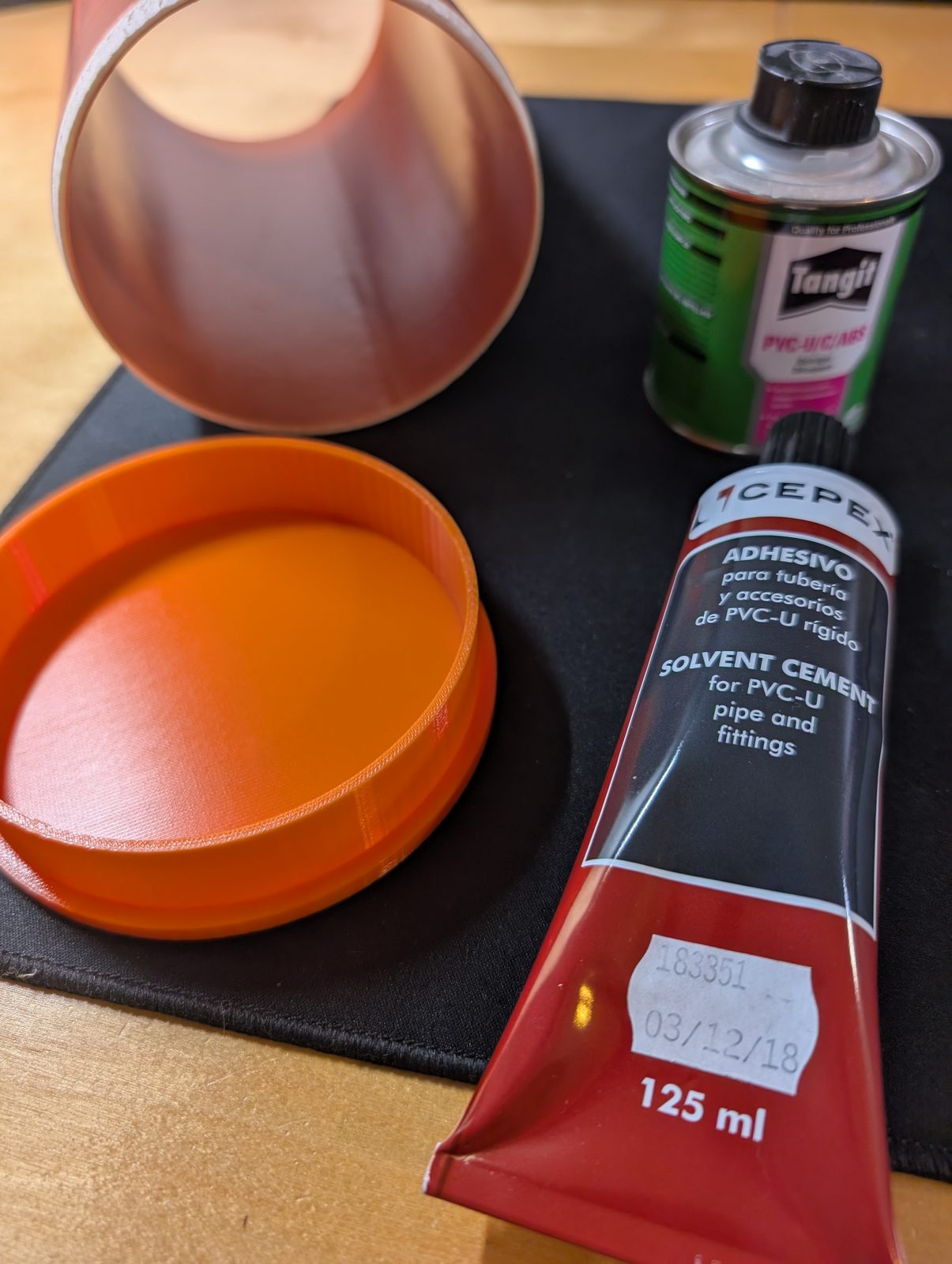
Why KG and not HT? KG pipe (the orange outdoor stuff) is PVC. HT pipe (the grey indoor stuff) is PP — and PP is, for practical purposes, unglueable. Nothing sticks to it, including the thing you were relying on to stick to it. PVC bonds beautifully to printed ABS with a PVC/ABS transition cement, which is the only reason this design has watertight joints instead of hopeful ones.
I discovered this the way I discovered everything else in this project.
The Divider, or: the part that actually matters
Here is the failure mode that cost me the most summers.
A float switch in a vessel with a pump has two things it can collide with: the pump, and the wall. It will find both. It will drift over, rest against something, and stay there — and a float that cannot rise is a float that says “empty” forever while the water climbs past it and out into the chimney.
You cannot fix this with a bracket. I tried brackets. The fix is architectural: give the float its own room.
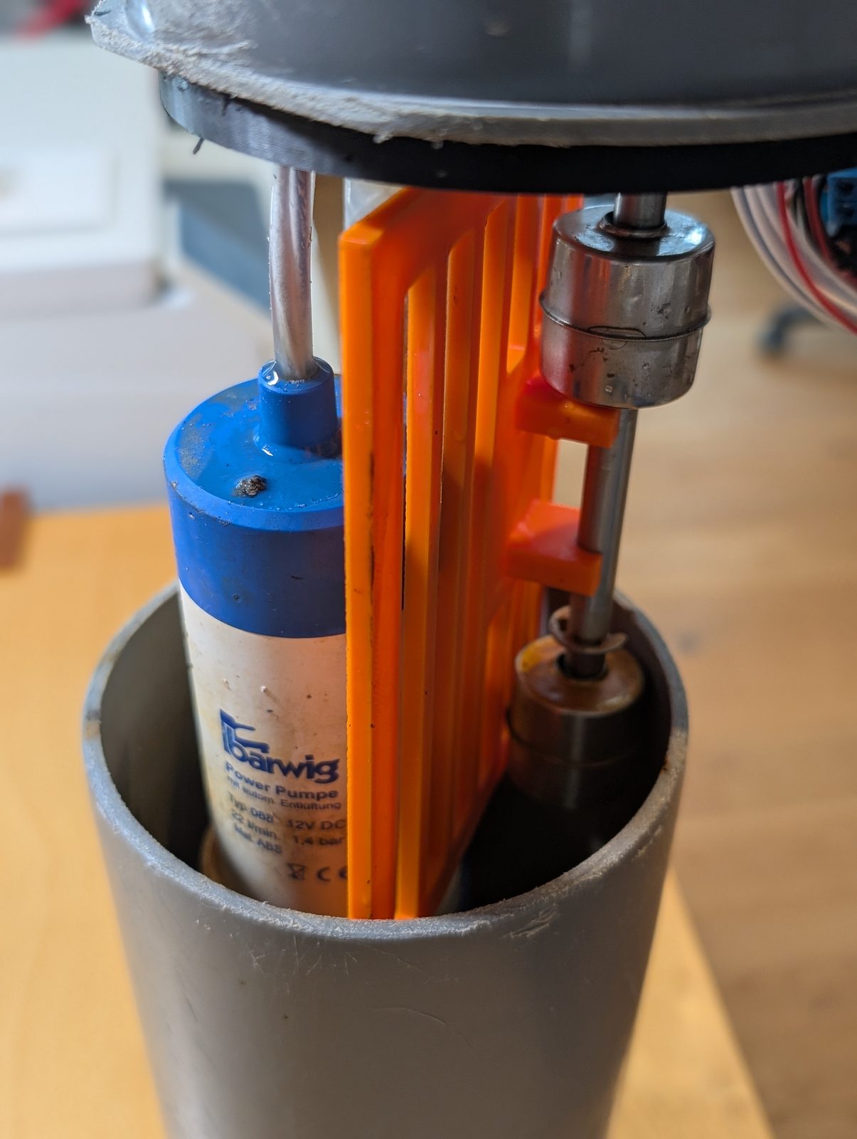
The divider is a 190 mm printed wall that drops into the insert and splits the pipe’s cross-section into a Ø43 mm float chamber and a pump chamber shaped like everything that’s left. The float is 40 mm across, which leaves it a millimetre and a half of clearance all the way round — enough to move freely, nowhere near enough to go anywhere interesting. It cannot reach the pump, it cannot reach the wall, it cannot do anything except go up and down.
The last 2 mm are the trick: the divider stops just short of the floor, so water passes freely underneath and the level in the float chamber is always the level in the pump chamber. Hydraulically it’s one vessel. Mechanically it’s two rooms with a very strict door policy.
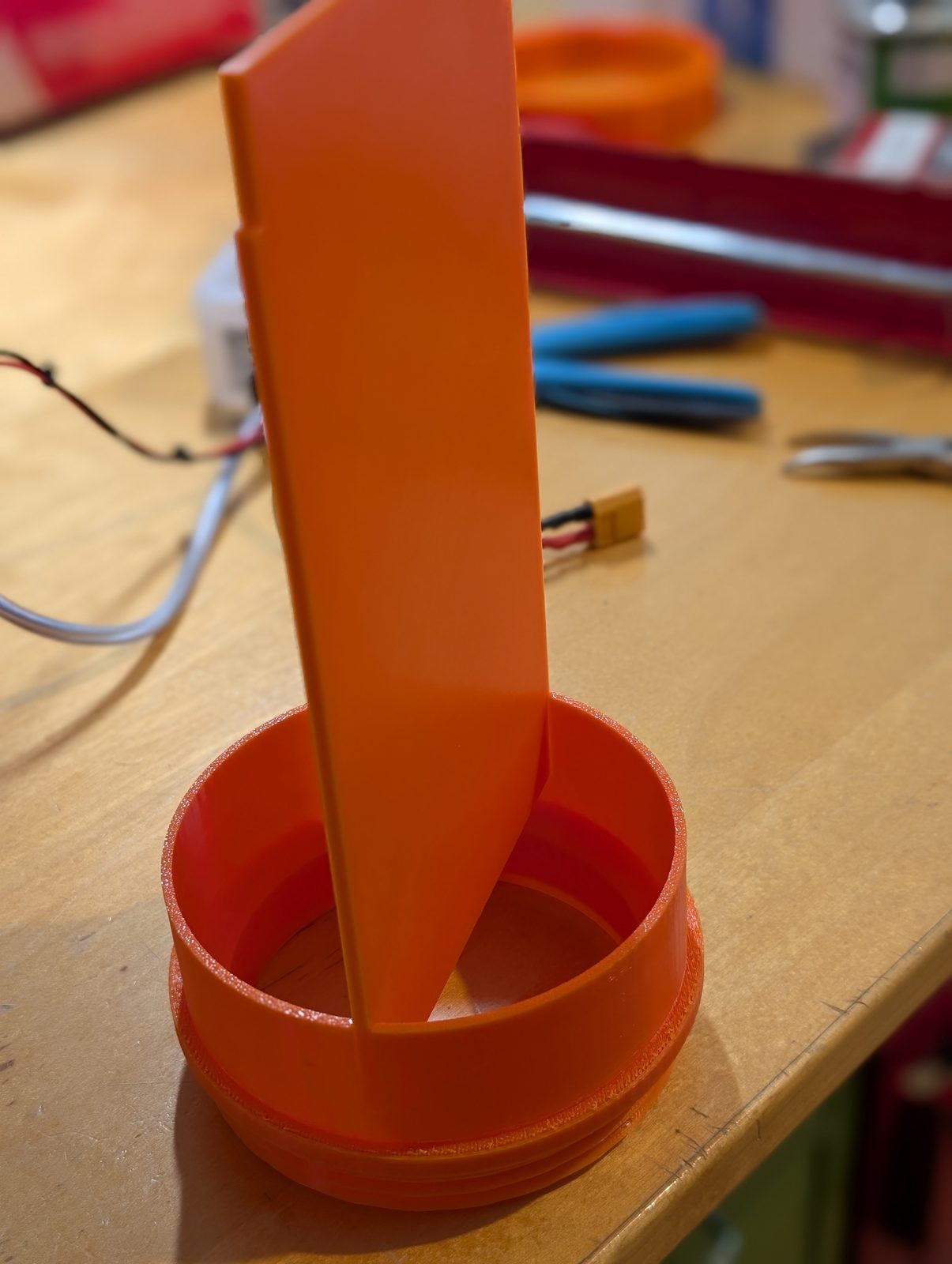
To keep the geometry honest, the divider’s bottom 20 mm is stepped down to Ø98 so it runs inside the floor’s rim rather than fighting it. And the lid can only go on one way — two asymmetric lugs on the insert rim (0° and 90°) engage pockets in the lid, so the float’s cable hole is always over the float chamber, and the lid can’t rotate while you tighten the ring. Both of those exist because earlier versions did the wrong thing at 23:00 on a Sunday.
The Electronics
There are no microcontrollers here. This is deliberate. I write software for a living, and precisely because of that I did not want a firmware bug standing between my flat and several litres of water.
- 12 V DC. A single supply for controller and pump.
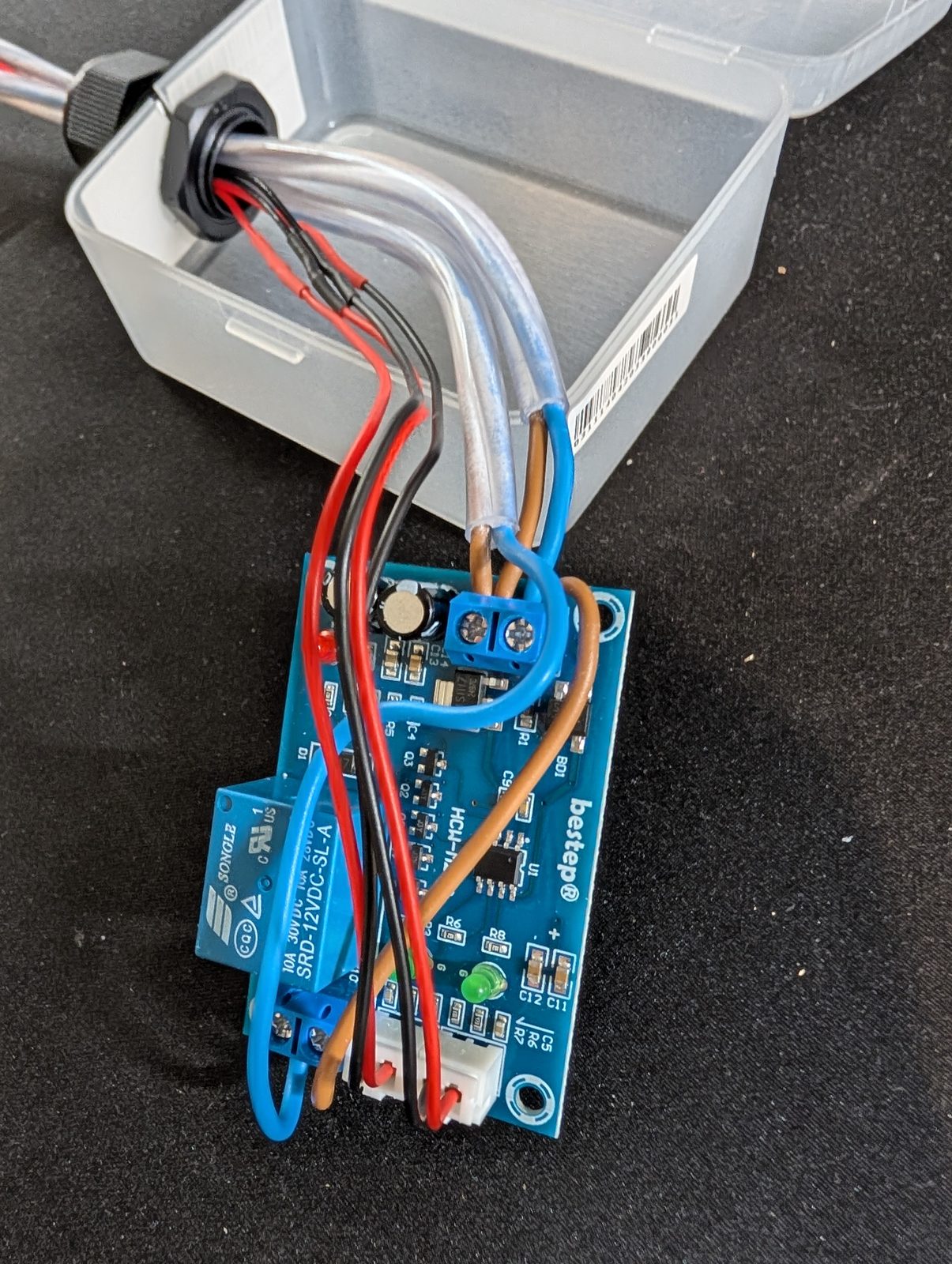
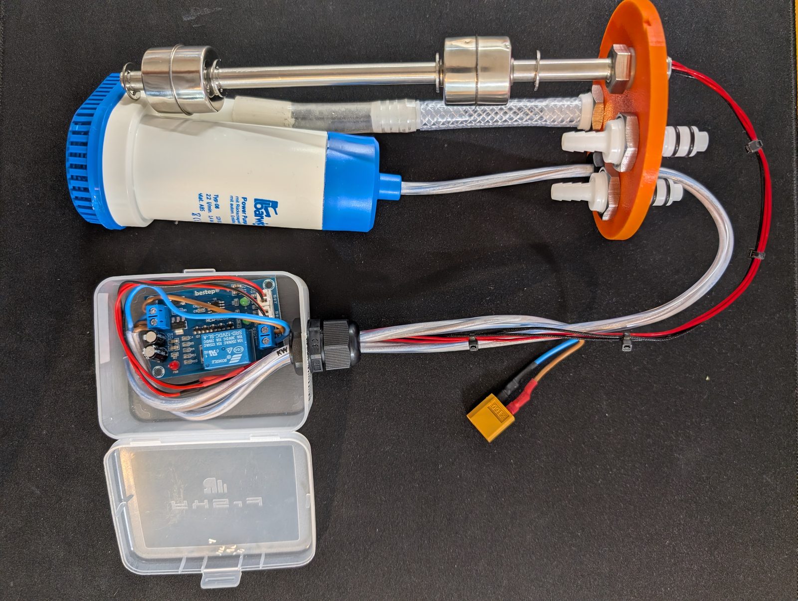
- XH-M203 water level controller — a relay board designed for a dual-float input. High float closes → relay latches → pump runs. Level drops → low float opens → relay releases. That’s the whole state machine, implemented in copper.
- Vertical stainless float switch, 200 mm, two float collars on one rod — the two switching points from law #2.
- The board lives outside the sump, in a small clear box beside it, fed through a PG cable gland in the lid. Water and electronics are separated by two independent seals and a change of address.
Printed Parts
Four parts, plus a choice of lid.
| File | Part | Job |
|---|---|---|
1_Einsatz.stl | Insert | Glues into the pipe, carries the external thread + O-ring groove, Ø86 access opening |
2_Trennwand.stl | Divider | Splits pump and float chambers, plugs 22 mm deep into the insert |
3_Ueberwurfring.stl | Union ring | Internal thread + grip ridges, presses the lid onto the O-ring |
4_Deckel.stl | Lid | 6 feedthroughs: 4× water, 1× power, 1× float cable |
5_Deckel_3Wasser.stl | Lid (3-water) | 5 feedthroughs, for one condensate line fewer |
6_Boden.stl | Floor | Closes the pipe, Ø110 flange flush with the pipe wall |
Both lids fit the same insert and ring, so pick one according to how many indoor units you’re collecting from. The fifth “part” is the pipe, and you buy that.
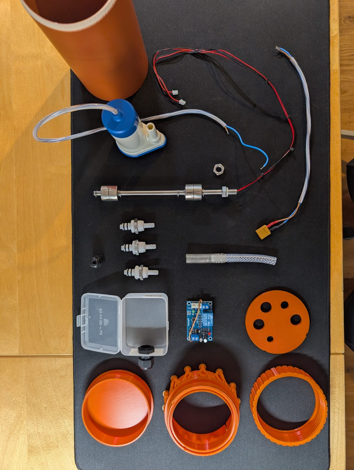
Bill of Materials
| Qty | Part | Note |
|---|---|---|
| 1 | KG pipe DN110 (PVC-U), 200 mm | Plain section, no socket. Wall 3.2 → Ø103.6 inside |
| 1 | PVC/ABS solvent cement | Bonds insert and floor into the pipe |
| 1 | O-ring 93 × 87 × 3 | Lid seal, ~20% compression |
| 2 + 2 | 1/4" bulkhead quick couplings (male + female) | Water in/out, Ø17.7 holes. Get the self-closing kind — see below |
| 1 | PG cable gland | Power cable, Ø12.7 hole |
| 1 | Ø10.5 feedthrough | Float switch cable |
| 1 | Vertical float switch, ≤ Ø40 float, ≤ 200 mm | Two switching points |
| 1 | Submersible pump, 12 V | Must fit the pump chamber and reach the roof |
The specific parts I used, and what they cost in August 2026:
| Item | Use | Price |
|---|---|---|
| Uadme float switch — stainless, vertical, 200 mm | The switch, in the float chamber | €14.11 |
| Barwig Typ08 submersible pump — 12 V, 1.4 bar, 22 l/min, Ø10 mm outlet, check valve | The pump, in the pump chamber | €59.90 |
| Hose connector set, barbed 6–10 mm | Hose joints and reducers | €8.38 |
| PG7–PG16 cable gland set, waterproof | Power and float cable feedthroughs | €8.56 |
| BBTUS 1/4" bulkhead coupling, female (2 pcs) | Water feedthroughs in the lid — self-closing | €23.18 |
| BBTUS 1/4" bulkhead coupling, male (2 pcs) | The other half | €20.16 |
Around €225 for the shopping list as it stands — which includes a second pump and a second float switch, because six years of this project has left me with firm views on spares.
If you economise anywhere, don’t do it on the pump. 1.4 bar is roughly fourteen metres of head on paper, against two floors of actual building. That margin is not vanity: it’s what stops a partially blocked line at the roof from turning into an overflowing sump at the bottom.
Print Settings
- Material: ABS. Non-negotiable for the insert and the floor, because those two get solvent-welded into PVC pipe. PETG and ASA are perfectly waterproof and completely un-gluable to PVC. PLA is fine for fit tests and nothing else.
- Watertightness: ≥ 4 perimeters and 40–60% infill, so the parts themselves are dense. The O-ring and the glands handle sealing to the outside world; the plastic just has to not weep.
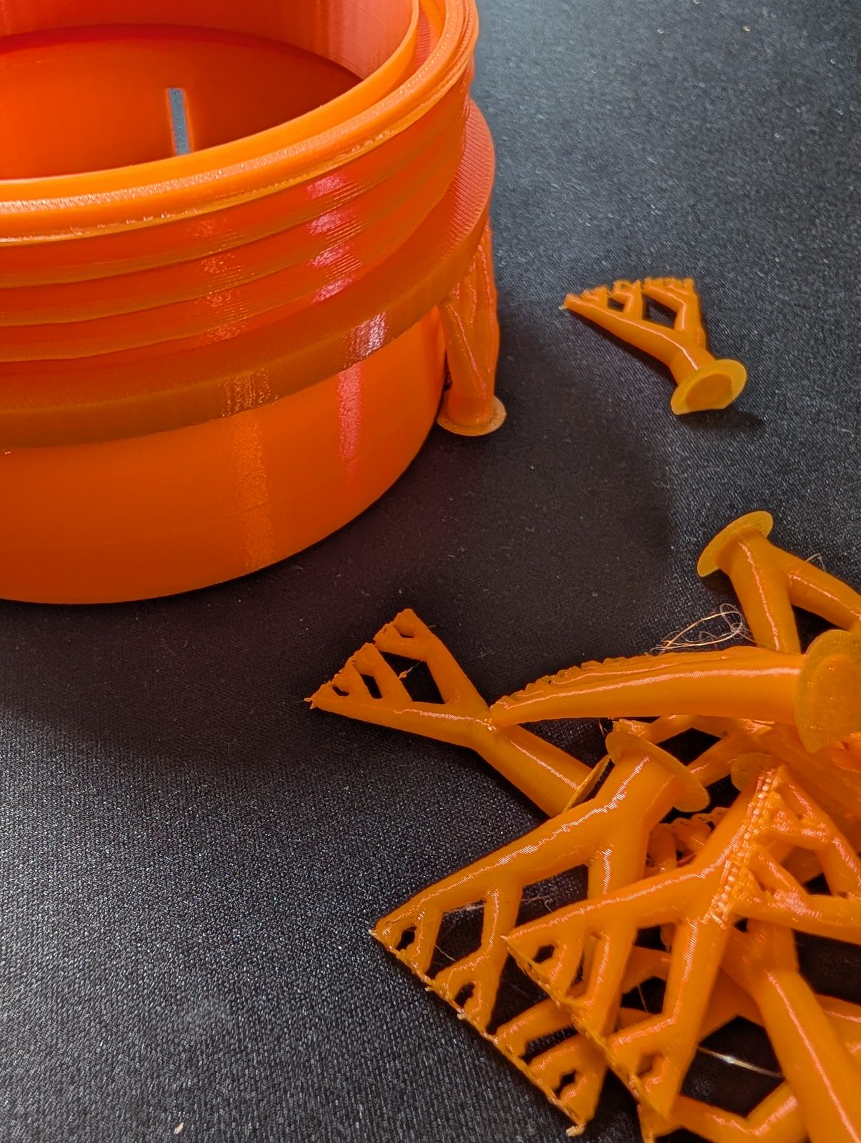
- Orientation: insert and union ring with the axis vertical, for even thread layers. Floor flange-down on the plate, rim up — a solid bottom skin and no supports. Lid and divider flat. The divider is 190 mm long and just fits a 256 mm bed.
- Print a fit test first — just the top ~20 mm of the insert and the ring. Threads are where hours go to die.
Assembly
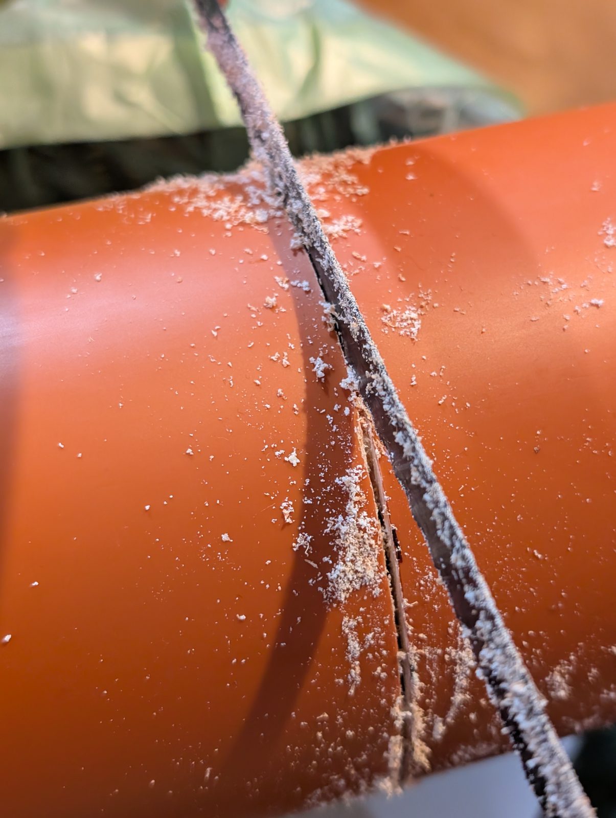
- Cut the KG pipe to 200 mm and deburr the cut edge. A hacksaw is fine. PVC dust gets everywhere and stays there.
- Glue in the floor from below — rim first, until the flange sits against the pipe end and finishes flush at Ø110. Run the cement all the way around.
- Plug the divider into the insert, stepped end downwards.
- Slide the insert (with divider) in from the top. The divider threads itself into the floor’s rim as it goes. Flange flush, then solvent-weld it to the pipe.
- Pump into the pump chamber, float switch into the float chamber, both through the Ø86 opening.
- Fit the feedthroughs into the lid from the inside, nuts tightened from the outside.
- Lay the O-ring into the groove on the insert rim.
- Drop the lid on. The two lugs find their pockets; it only goes on one way.
- Screw the union ring down until the lid sits flat on the insert rim — hard stop, correct O-ring compression, done.
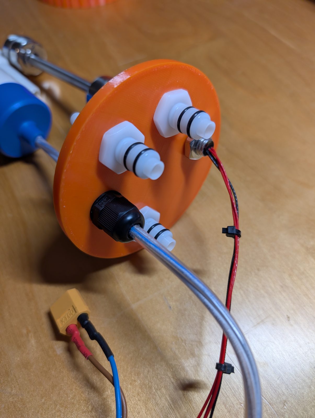
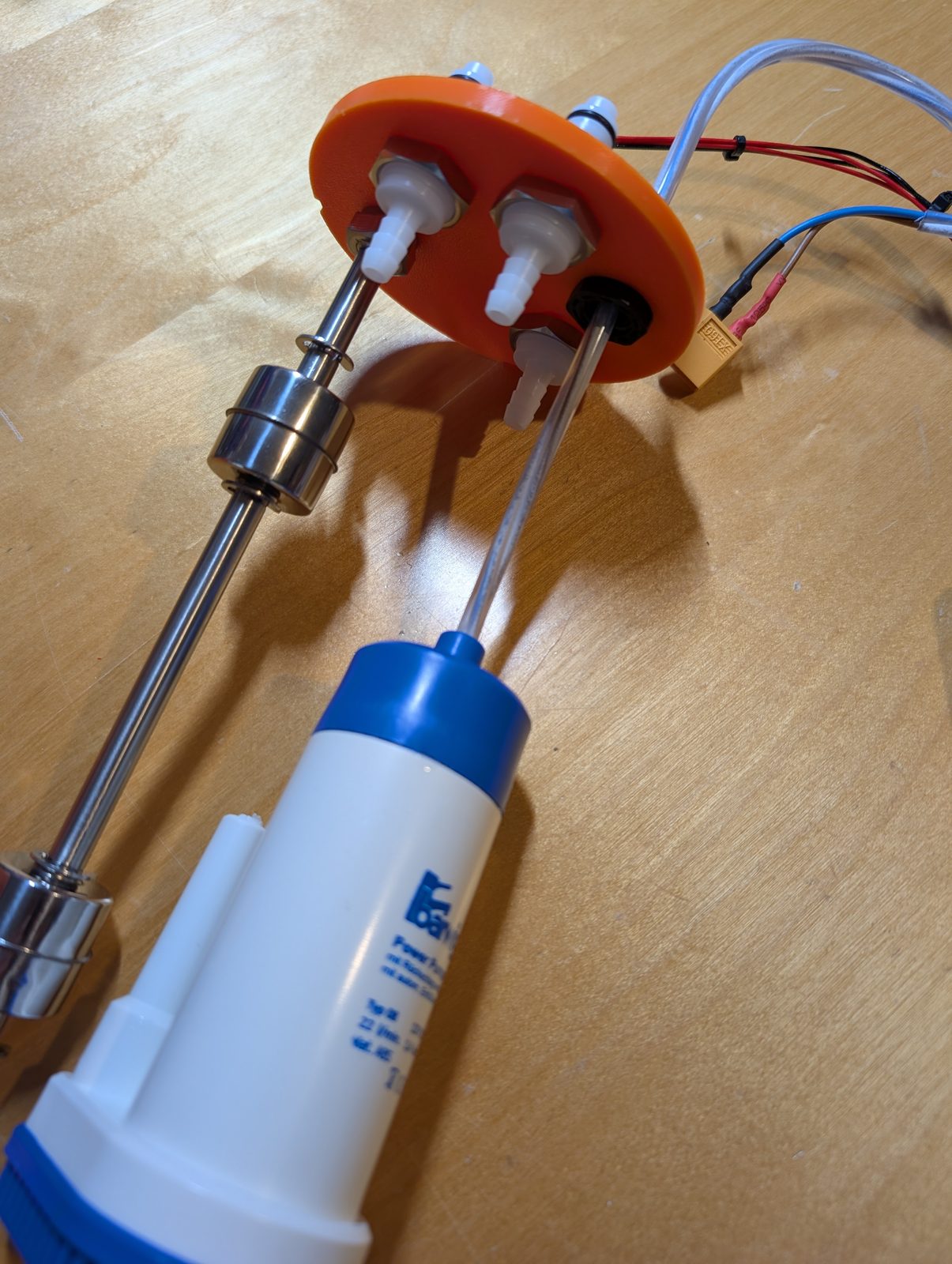
The last point deserves its own sentence, because it’s the maintenance decision I’m happiest with: the lid is the chassis. Pump, float, hoses and every wire are attached to it. Unscrew one ring, lift, and the entire mechanism comes out of the chimney as a single object — instead of being fished out of a wet shaft by feel, at midnight, which is the alternative I have extensive personal experience with.
Which brings me to the one line item I’d defend in court: the couplings.
Four bulkhead quick couplings cost about €43 — the second most expensive thing in the build after the pump, and roughly ten times what a barbed fitting and a hose clip would cost. A barbed fitting would work perfectly well. It would also mean that every time I want to look at the pump, I first have to disconnect four hoses that are full of water, inside a chimney, over a floor.
These are self-closing. Pull the collar and both halves shut themselves: the hose keeps its water, the sump keeps its water, and precisely nothing arrives on the floor. Unclip four, unscrew the ring, lift the machine out, carry it to a table. No bucket, no towel, no hose, no siphoning, no swearing.
I have spent six years building a device whose entire purpose is to stop water appearing where it shouldn’t. Paying €43 so that servicing it doesn’t spill water on the floor is not an extravagance. It’s the single most consistent lesson of the whole project, finally applied to the maintenance instead of the mechanism.
Does It Work?
Bench test first, on the table, dry: slide the float collars up the rod by hand and watch the relay latch and release.
Six seconds of video and about six years of context. High float up, LED on, relay clicks, pump would run. Level falls, low float drops, relay releases. That’s it. That’s the entire behaviour I had been failing to achieve since 2020.
Then into the chimney, hoses connected, door closed. And then the real test, which is not a test at all but a summer: it collects, it fills, it runs for a few seconds, it stops. Nobody hears it. Nothing in the flat knows it exists.
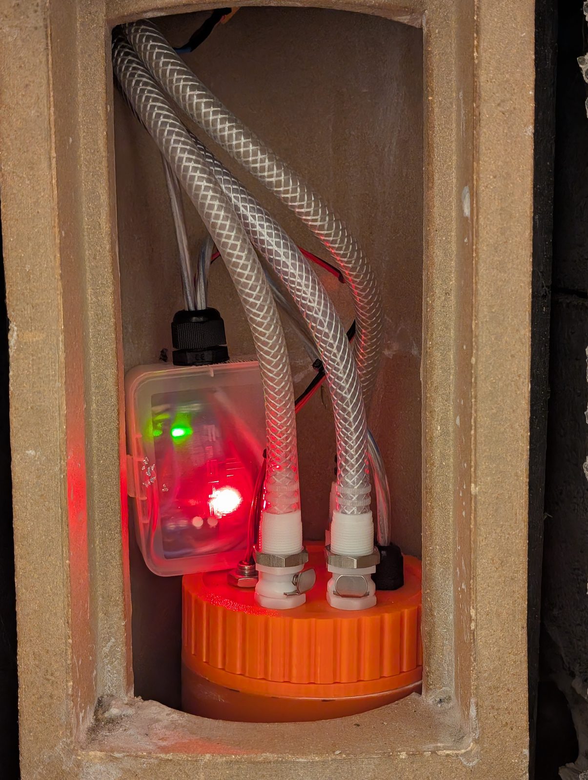
I have not siphoned anything with my mouth since.
Key Dimensions
For anyone rebuilding this against a different pipe or a different float:
| Feature | Value |
|---|---|
| Outer envelope | Ø110 mm — never exceeded, anywhere |
| Pipe (KG DN110, PVC-U) | Ø110 outside / Ø103.6 inside, 200 mm long |
| Insert spigot | Ø103.2 outside × 30 mm (0.4 mm glue gap in the pipe) |
| Floor | Ø110 × 5 flange, Ø103.2 rim, 20 mm inwards |
| Divider | 190 × 3 mm, bottom 20 mm stepped to Ø98, 2 mm clear of the floor |
| Access opening | Ø86 mm |
| Thread | Ø102 outside / Ø98 core, 4 mm pitch, right-hand |
| O-ring groove | Ø87 inside / Ø93.8 outside, 2.4 deep × 3.4 wide |
| Float chamber | Ø43 mm |
| Lid holes | 4× Ø17.7 · 1× Ø12.7 · 1× Ø10.5 on a Ø57 bolt circle, 60° apart |
| Free internal volume | 170 mm of pipe below the insert |
| Assembled height | 235.5 mm |
Version History
Each of these is a summer.
v5 — KG pipe and a printed floor. Moved from HT (PP) to KG (PVC) so the printed parts could actually be glued in. Inner diameter went from Ø104.6 to Ø103.6, so the insert and divider came down from Ø103.8 to Ø103.2 — previously the insert only went in with violence, which is not a fit, it’s a threat. Pipe shortened to 200 mm to match the 200 mm float switch. New printed floor replaces the glued-in PVC disc. Divider shortened 235 → 190 mm and stepped so it passes through the floor’s rim.
v4 — Hole sizes. Lid holes +0.5 mm. See above, sigh.
v3 — Anti-rotation. Two lugs on the insert rim, asymmetric at 0°/90°, engaging pockets in the lid. The lid now fits in exactly one orientation and stops trying to rotate with the ring while you tighten it.
v2 — After the first test print. Thread made longer and looser (~0.55 mm play instead of 0.4). Grip ridges on the union ring, inside Ø110. Divider socket deepened from 4 to 22 mm and tightened, so it holds without glue. Second lid variant with three water inlets.
v1 — First attempt. Printed, tested, informative.
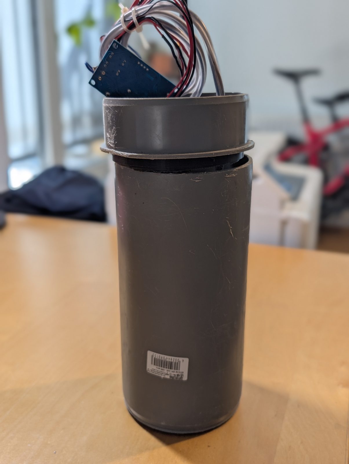
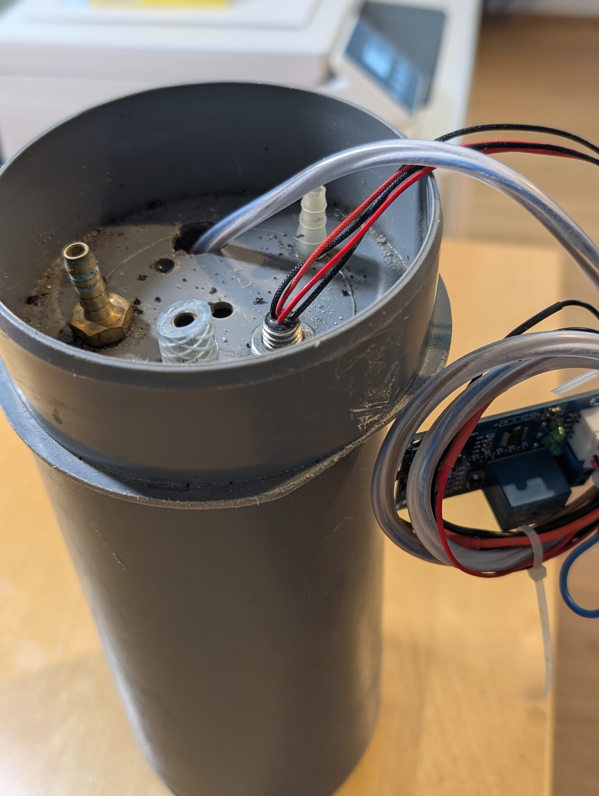
And behind v1, unnumbered and unphotographed except for these, the actual six years: the grey HT-pipe prototypes with brass barbs and horizontal floats and every leak I have described above.
Status
Running. Installed at the bottom of the chimney, collecting from the indoor units, pumping to the roof, inaudible from anywhere a person sleeps.
Files — STLs, the Bambu Studio projects and the full German build notes — are on GitHub at altbrot/pumpensumpf. Print them, build one, cut the six years down to a weekend. The Fusion 360 document is a direct model with no timeline and no user parameters, which means the dimensions live in the geometry itself. Change one and you will find the others by hand. I’d apologise, but honestly, after six years the model was never the hard part.
Here’s what I actually took away from this, beyond a working pump.
Every failure was the same failure wearing a different costume: I kept trying to make an unreliable arrangement reliable by adding care. Better sealing on a joint that shouldn’t have existed. A bracket for a float that needed a room. A cleverer sensor instead of a dumber one. None of it worked, because care is not a mechanism — it evaporates the moment you stop paying attention, and a condensate pump runs for four months while you pay attention to something else.
What finally worked was giving every part a place where the failure was geometrically impossible. The float can’t jam because it can’t reach anything. The lid can’t seat wrong because it only fits one way. The ring can’t be over-tightened because it hits a stop. The electronics can’t get confused because there’s nothing in there capable of confusion.
From the outside it’s a piece of orange pipe with a lid on it, at the bottom of a chimney, where nobody will ever see it. It is one of the most satisfying things I have ever built.
And it looks fantastic.